| Electromagnetic Latching Safety Door Lock Switch
|
| Ordering Information |
| Image Display | Switch Model | Contact Configuration | Conduit Opening/Connector | Type | |
| Door Lock +Handle | Door Lock | ||||
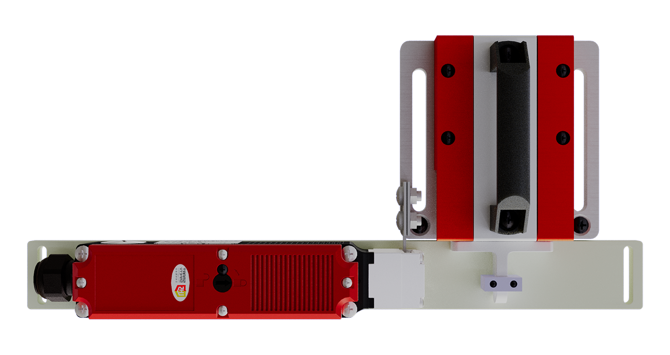 | D3SL-S | 2NC/1NC+2NC/1NO | M20 Waterproof Connector | Power-On Unlocking | |
 | D3SL-D | 2NC/1NC+2NC/1NO | M20 Waterproof Connector | Power-Off Unlocking | |
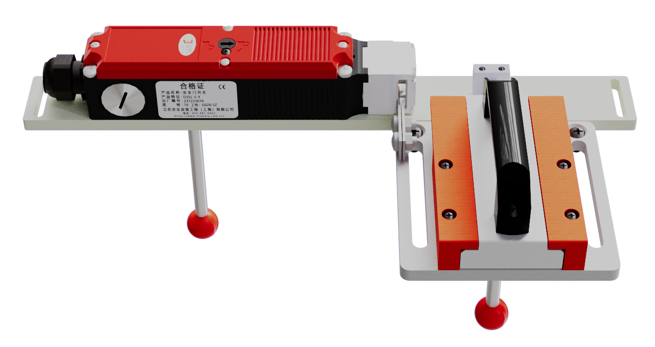 | D3SL-S-Y | 2NC/1NC+2NC/1NO | M20 Waterproof Connector | Power-On Unlocking+Rear Unlocking | |
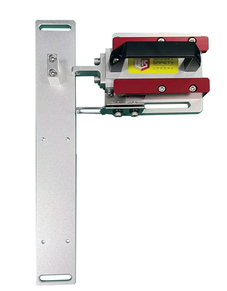 | BS03 | Metal | / | Ordinary Handle | |
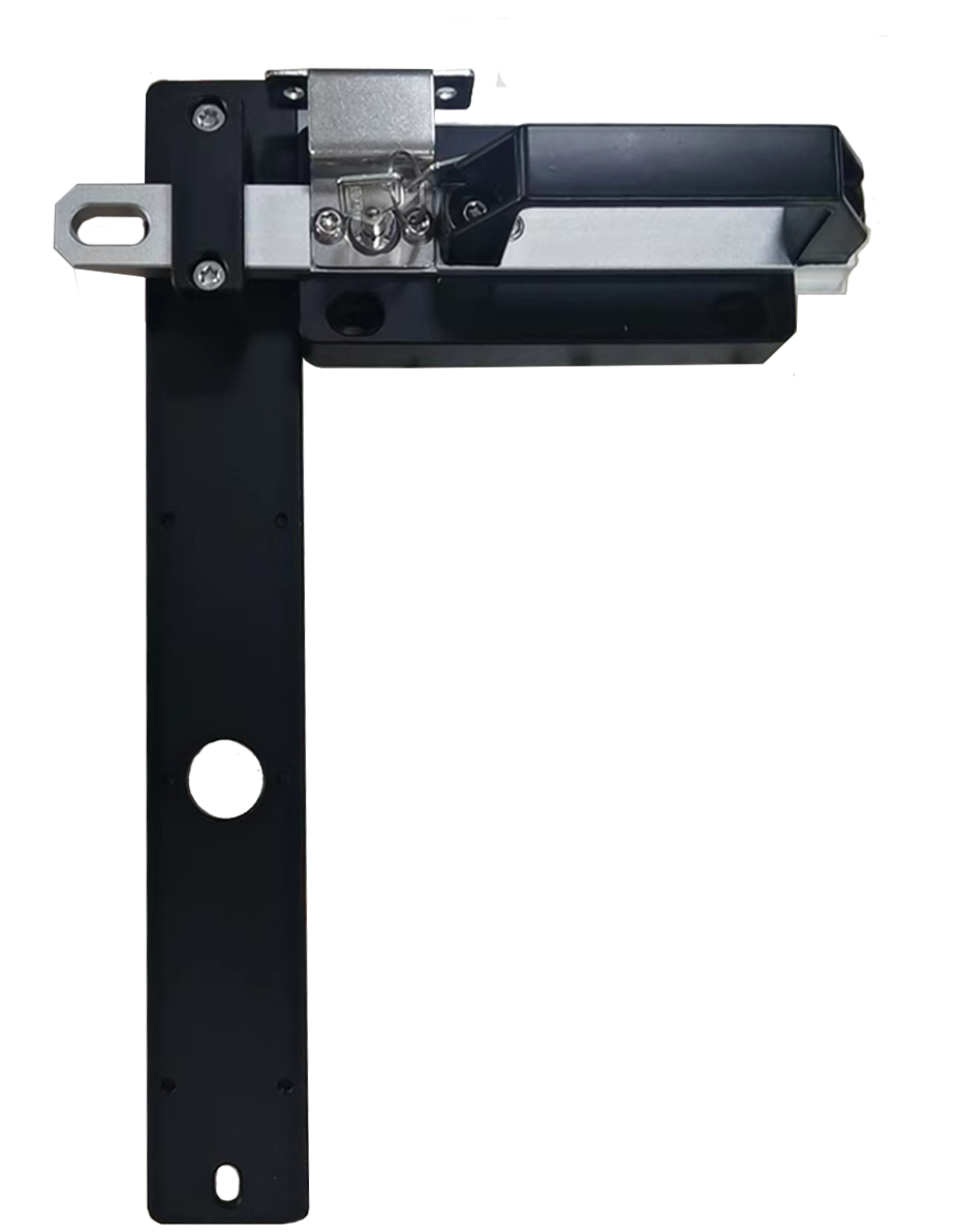 | BS04 | Metal | / | Keyed Handle | |
 | BS08 | Metal | / | Rear-Release Handle | |
Instructions: | D3SL is recommended for use with handles | ||||
| Locking tongue type |
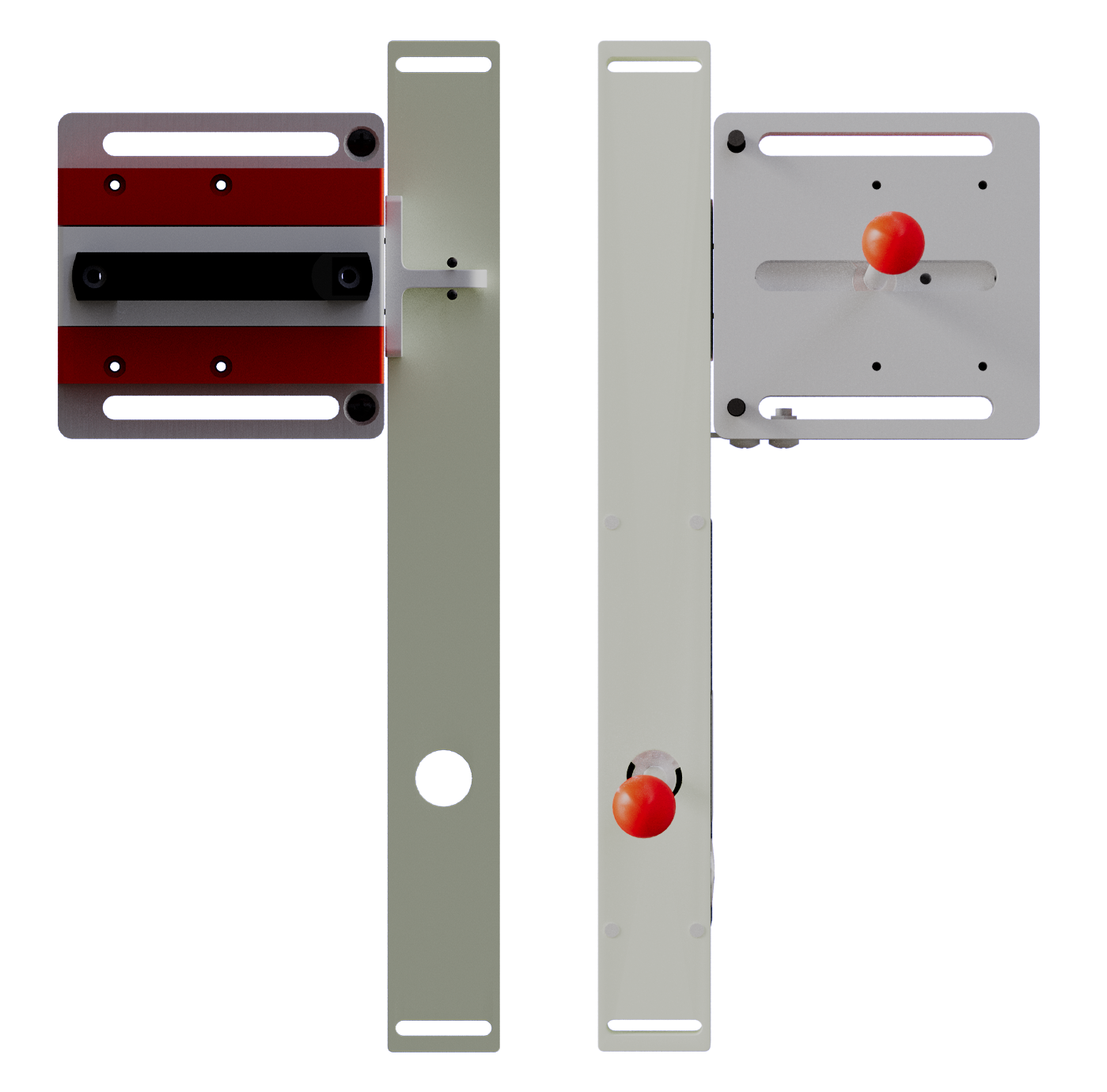
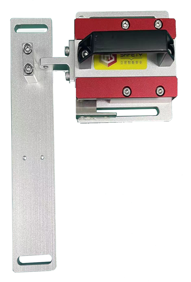
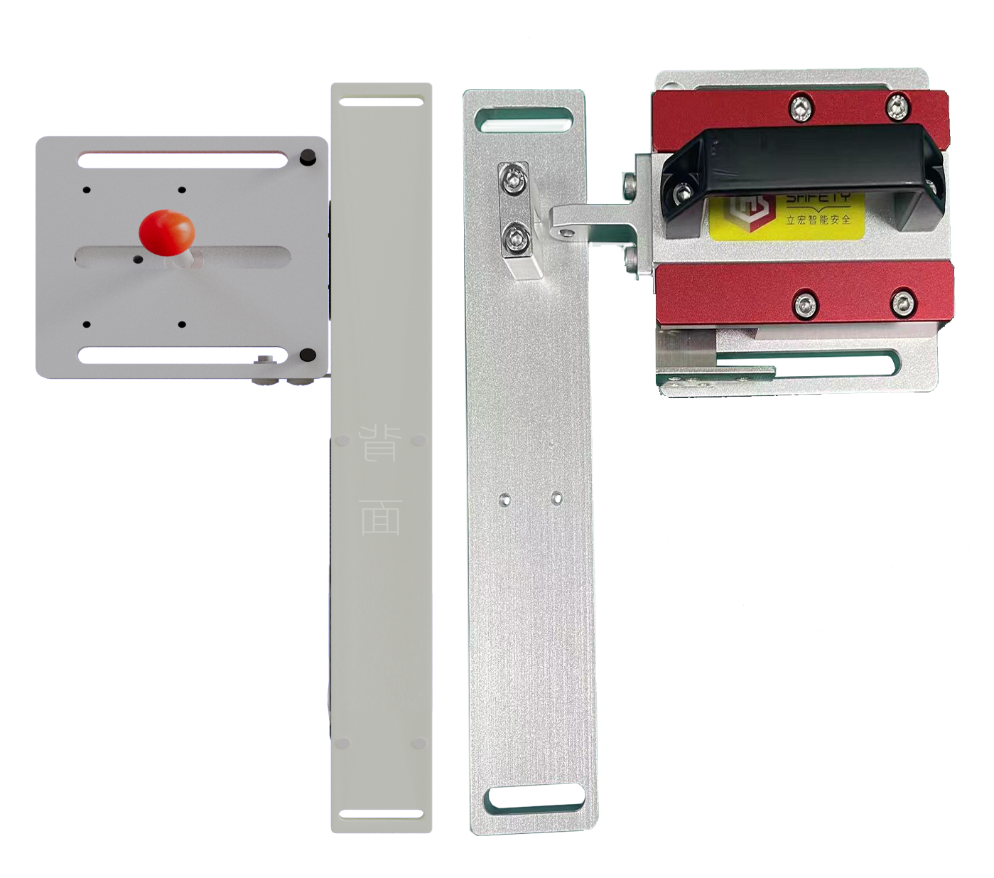
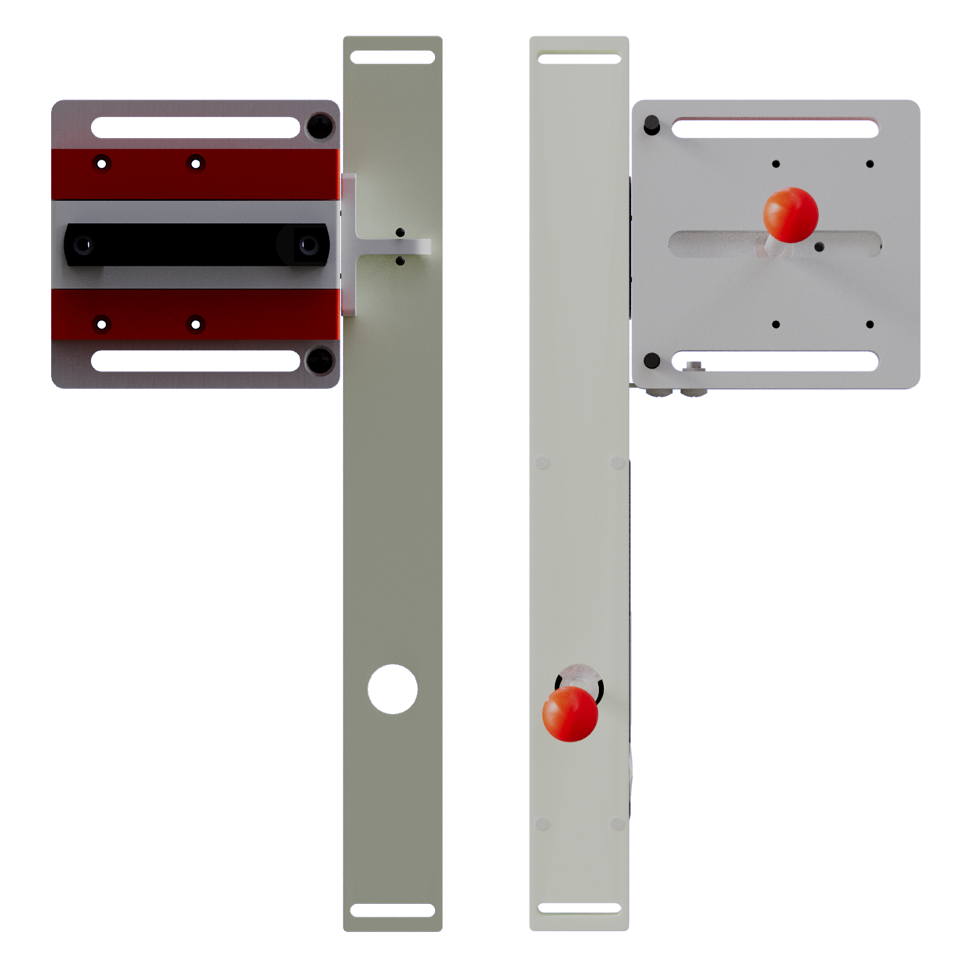
Direct-Insertion Mounting Type Z | Long-L Mounting Type ZL | Wide-Mount Type K | Short-L Mounting Type KL |
|
|
|  |
| Safety Latch/Handle |
Safety Latch BS02 | Safety Latch BS01 | Safety Latch BS03 | Safety Latch BS08 | Safety Latch BS04 | |||
 |  |  |  |
| |||
 |
|  |   |
| |||
| Contact Capacity |
Rated Voltage | 30V | 250V | ||
Rated Current | AC | Resistive Load(AC-12) | — | 4A |
Inductive Load(AC-15) | — | 2A | ||
DC | Resistive Load(DC-12) | 2A | 0.8A | |
Inductive Load(DC-13) | 1A | 0.4A | ||
| Performance |
| Security Certificate | Mechanical reliability | B10d = 2.5×10⁶ operating at a load of 100 mA. |
| Safety data | 8 cycles per hour, 24 hours per day, 365 days per year. MTTFd is 356 years | |
| Protection Rating | IP67 | |
Service Life*1 | Mechanical | No less than 1 million times |
No less than 100000 times(AC-12 250V 4A) | ||
Electrical | ||
No less than 1 million times(24V AC/DC 100mA) | ||
Operation progress | 0.5m/s | |
Operation frequency | Maximum 30times/min | |
Forced disconnection force*2 | Minimum 60N | |
Forced disengagement of travel*2 | Minimum 10mm | |
Minimum applicable load | 24V DC 4mA | |
Degree of pollution (operating environment) | Pollution Degree 3 | |
Contact Capacity | 24V(DC13 4A)/230V (DC15 4A) | |
With Electromagnetic Coil | Rated Voltage:DC 24V Rated Current:0.31A Insulation Class: Class B | |
Ambient Temperature | -10-40℃ | |
| Model and contact composition |
Model | Contact Configuration: | Contact Form | Action Mode |
D3SL-S | 2NC/1NC+2NC/ 1NO |  |  |
| D3SL-D | 2NC/1NC+2NC/ 1NO |  |  |
| Magnetic Coil |
rated voltage | DC24V+10% |
rated current | 0.4A |
insulation grade | Class B |
| Power-On Unlocking Schematic Diagram |
Action State | State 1 | State 2 | State 3 | Manual Unlocking State |
Door Closed State Equipment Startup Coil De-energized | Door Closed State Equipment Not Startable Coil Energized | Door Open State Equipment Not Startable Coil De-energized | Door Open State Equipment Stop Coil De-energized | |
Guard Door Status Diagram | 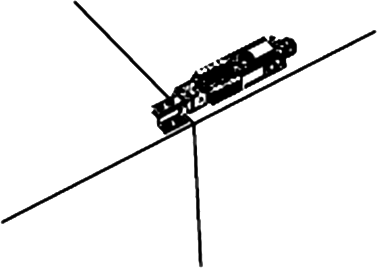 | 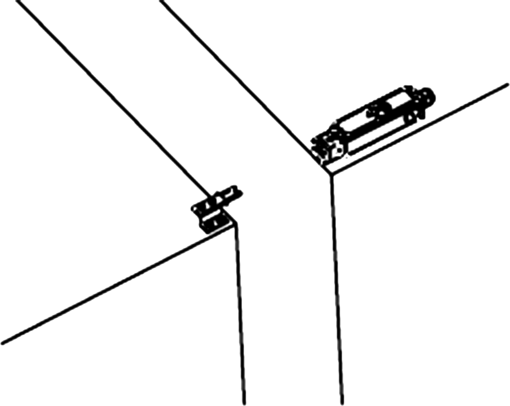 | 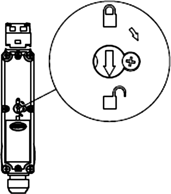 | |
Contact Electrical State Diagram |
|
|  |  |
| Power-Off Unlocking Schematic Diagram |
Action State | State 1 | State 2 | State 3 | Manual Unlocking State |
Door Closed State Equipment Not Startable Coil De-energized | Door Closed State Equipment Startup Coil Energized | Door Open State Equipment Not Startable Coil De-energized | Door Open State Equipment Stop Coil De-energized | |
Guard Door Status Diagram |  |  |  | |
Contact Electrical State Diagram |  |  |  | |
| Internal Structure and Wiring Diagram |
 |  |  |
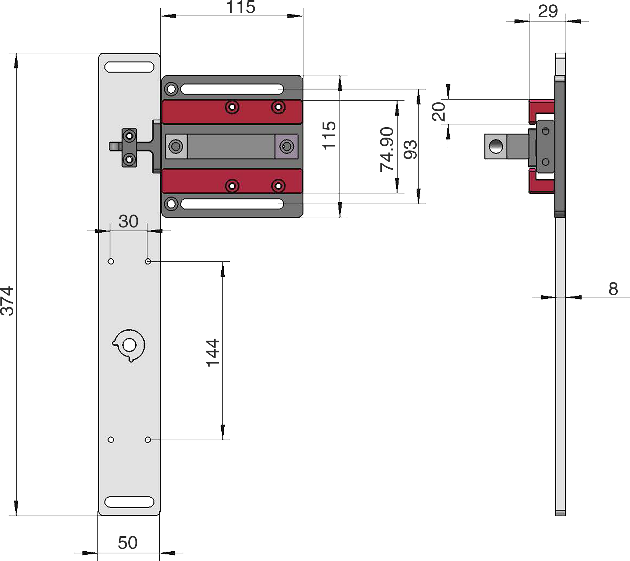
| External Dimensions and Installation Size |
External Dimensions and Installation Size |
 |
| Head Installation Direction |
Installation Direction | Head Direction Adjustment | The head of the safety door switch can be adjusted in direction to accommodate a wider range of installation environments. The housing position remains unchanged; only the direction of the head is altered. |
 |  |
| Auxiliary Unlocking Instructions |
 | When the safety door switch is operating normally, the arrow points to the "Locked" mark, and the anti-rotation screw must be in a tightened state. In special circumstances such as equipment power-off or malfunction, if it is necessary to open the guard door, the screw next to the arrow knob should be loosened first. Then, use a tool to turn the arrow knob to the "Unlocked" mark. At this point, the safety door switch is unlocked, the latch pin can be removed, and the guard door can be opened. |
| Safety Interlock Switch Selection Table |
Safety Door Lock Switch
| Electromagnetic Door Lock Switch
| Electromagnetic Door Lock Switch
| AI Intelligent Safety Door Lock
| ||
Selection Criteria | Model | D3-B2S | D3SL | D3NL | AI box-F |
Contact Configuration | 2NC/1NO | 2NC/1NC+2NC/1NO | 4NC/2NO | 2NC/1NO+2NC/1NO | |
Enclosure | ABS Plastic | ABS Plastic | ABS Plastic | Metal | |
Head Installation | 4 directions | 4 directions | 4 directions | Left and Right Directions | |
Locking Force | 130N | 2000N | 2000N | 2000N | |
Protection Rating | IP67 | IP67 | IP67 | IP67 | |
Features | Operating key adjustable | ◼ | ◼ | ◼ | |
24VDC Electromagnetic Latching / Mechanical Unlocking | ◼ | ◼ | ◼ | ||
Door Monitoring | ◼ | ◼ | ◼ | ◼ | |
Safety Certification | Safety Certification CE Certification | ◼ | ◼ | ◼ | ◼ |

Lihong Safety Equipment Engineering (Shanghai) Co., Ltd.
E-Mail: info@lh-safety.com
Address: 581 Xiuchuan Road, Chuansha Town, Pudong New District, Shanghai
(Greenland East Coast International Plaza-Room A 313)
Copyright © Lihong Safety Equipment Engineering (Shanghai) Co., Ltd. ICP19034341-1 Technical Support: lanjujing